Glowing Framework Logo Project
This project started because I wanted to recreate the old light-up apple logos that Macbooks used to have, and I have a super modular, repairable laptop, so I figured I would give it a go.
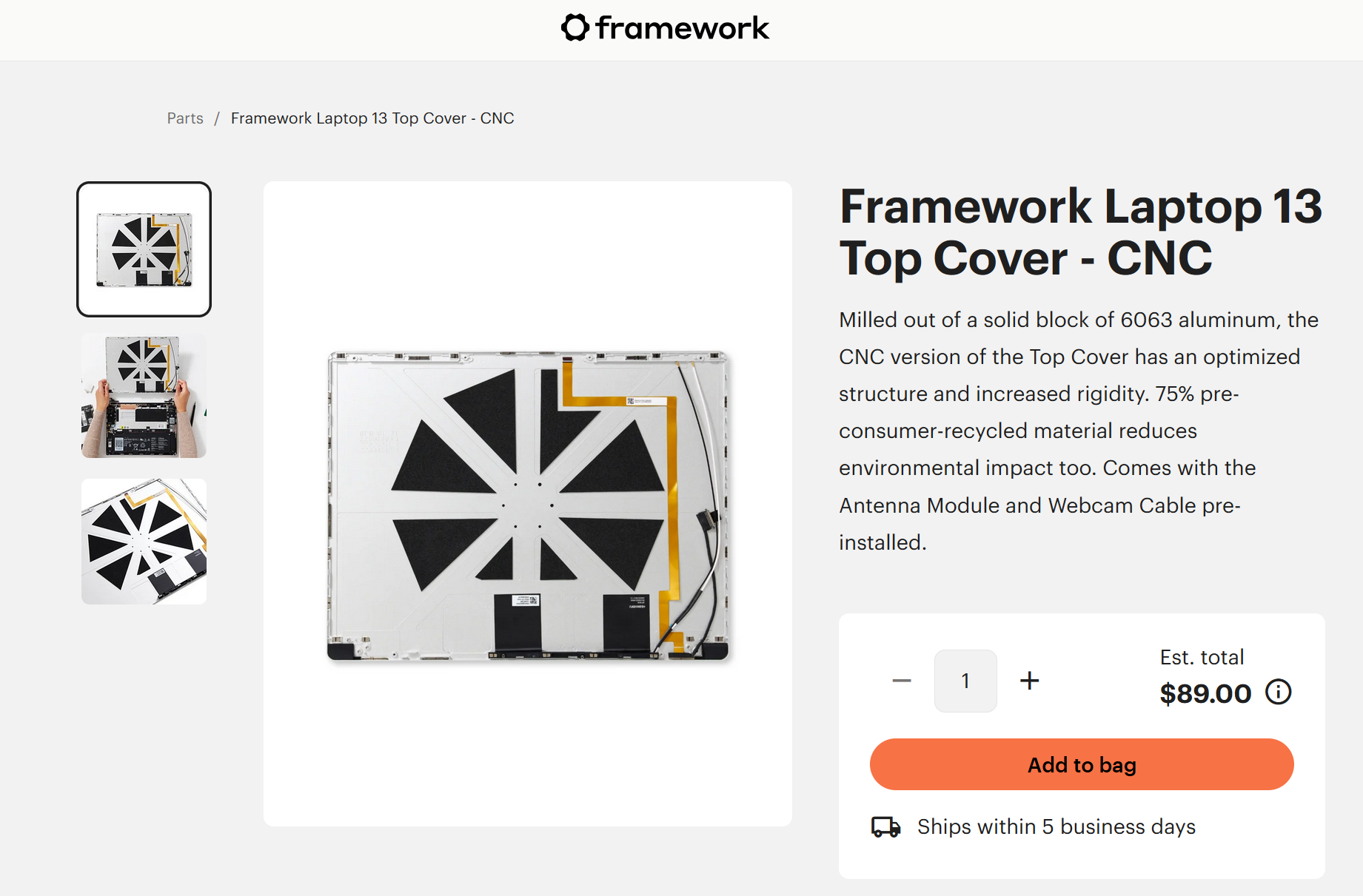
I had to start by ordering a new top cover (the upper aluminum piece), but there was decent reason to do that anyway, because my old one was full of stickers, and I'm a huge fan of stickers, so I wanted a new place to put them all, and Framework had redesigned the top cover to be both lighter and stiffer, so it was kinda an upgrade.
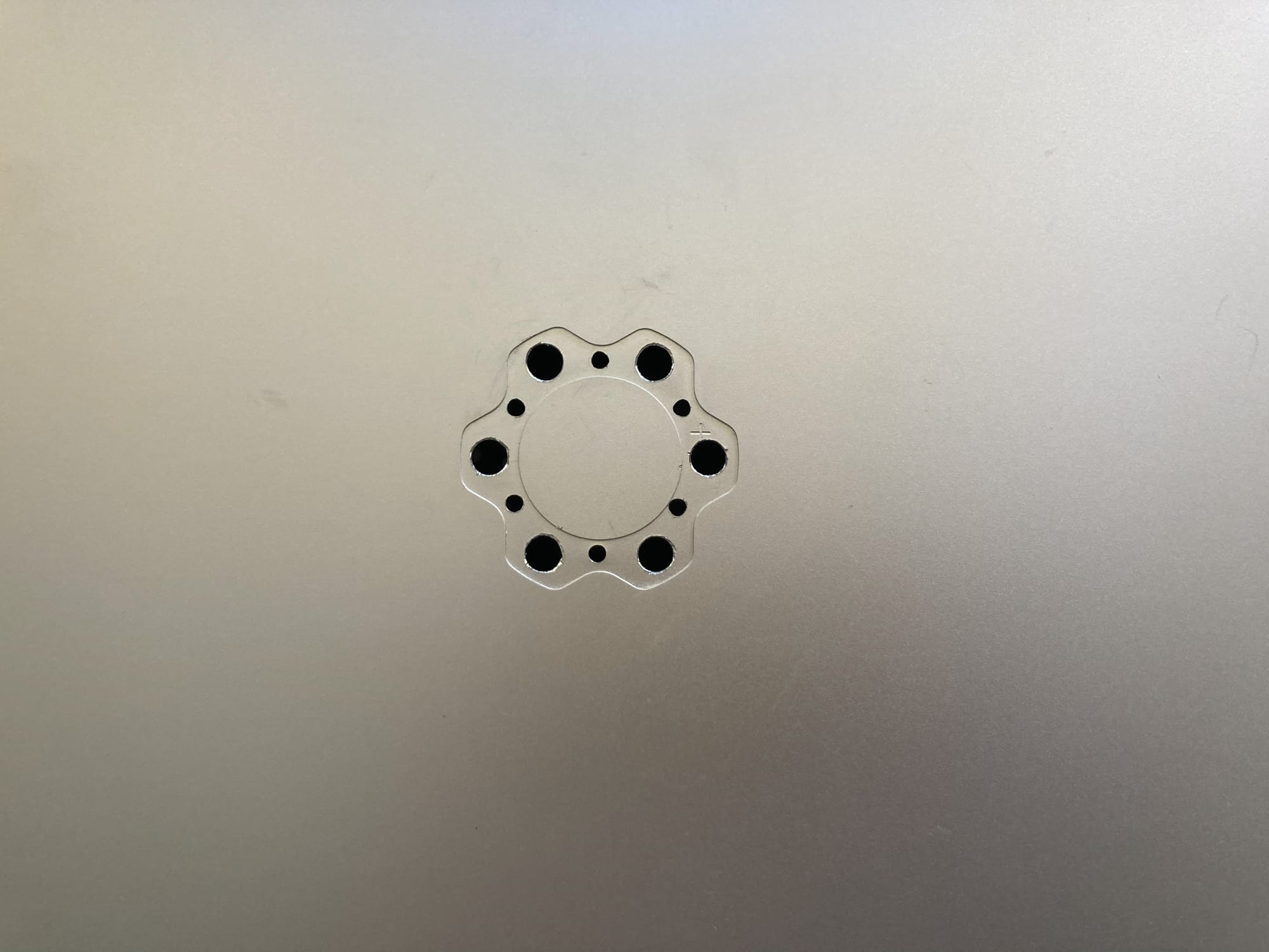
The top cover normally has a piece of black plastic where the logo sits on the outside, so I dissolved the adhesive that was holding it in, and pulled that piece out, which opens up the 6 holes in the larger sections of the logo.
I used these as a guide, and measured out the size & shape as best I could.
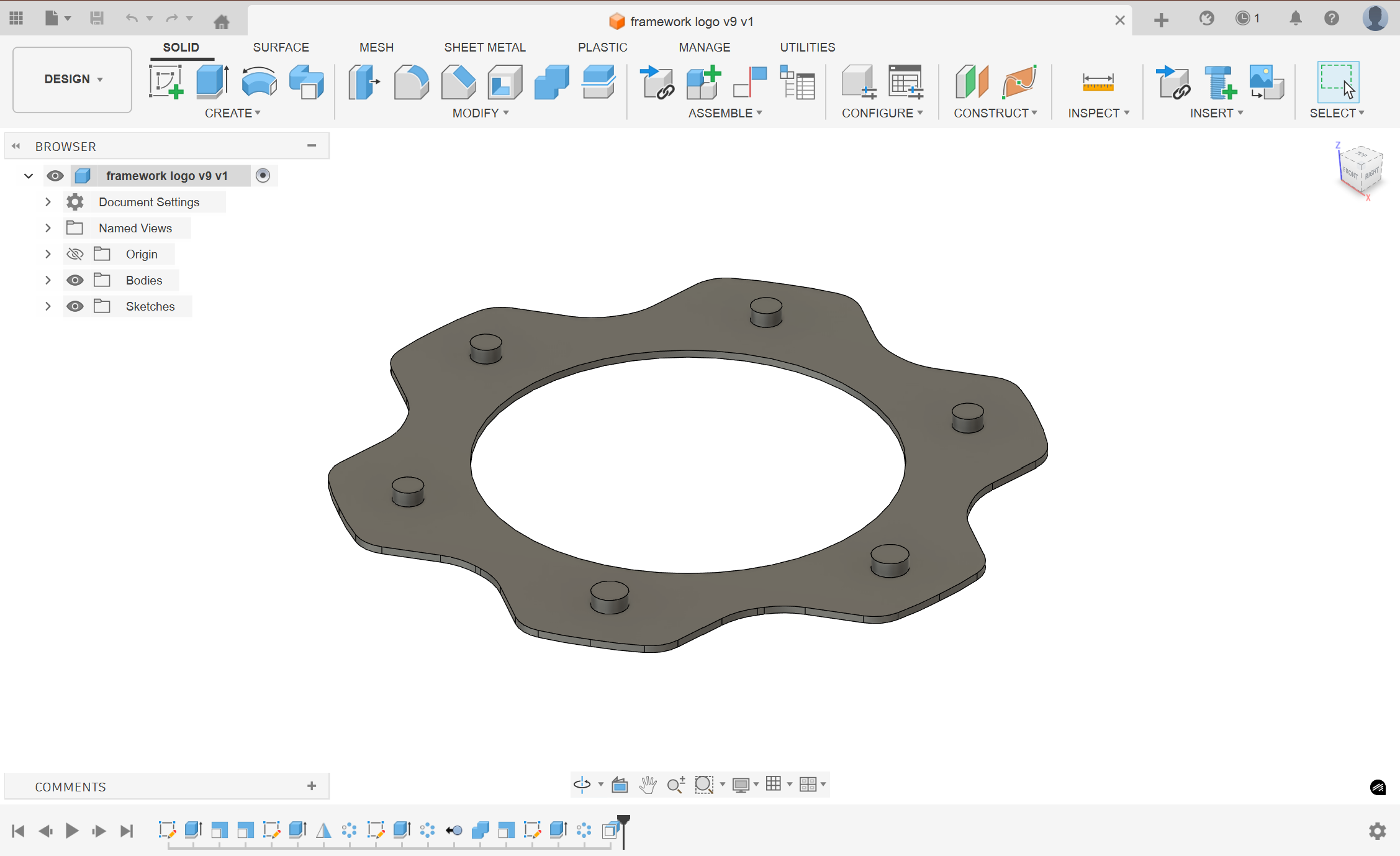
I remember referencing someone else's design of the logo for some of the measurements, but I don't think I ever saved who's they were or where I got them, so here's a vague credit to... someone in the framework community.
I think the pegs on this design were from that reference, and I had the idea to use them originally to sit flush against the LEDs within the holes and provide better light transfer, but as you'll see in just a second, getting the holes perfectly aligned takes far more time and precision than I think this project needs, or that I put in.
I designed the cutout and board for 12 holes, so that the light would be better spaced out and more diffuse.
I would be lying if I said I remembered which drill bit sizes I used for this, but just... ones that are close enough to what I designed.
I'm realizing as I write this that I've lost the file that I used for the PCB. I can access the manufacturing outputs in my order history from JLCPCB (more on them in a second), but the actual design file that I used is gone.
I wiped my laptop, and Altium (PCB design software I use) doesn't save its stuff in the normal documents folder, it saves it in the "public documents" section, and I didn't have that backed up. Altium is the only software that does this, which is kind of annoying, but alas. I shouldn't need the file for anything in the future, but it means I can't get any screenshots or references.
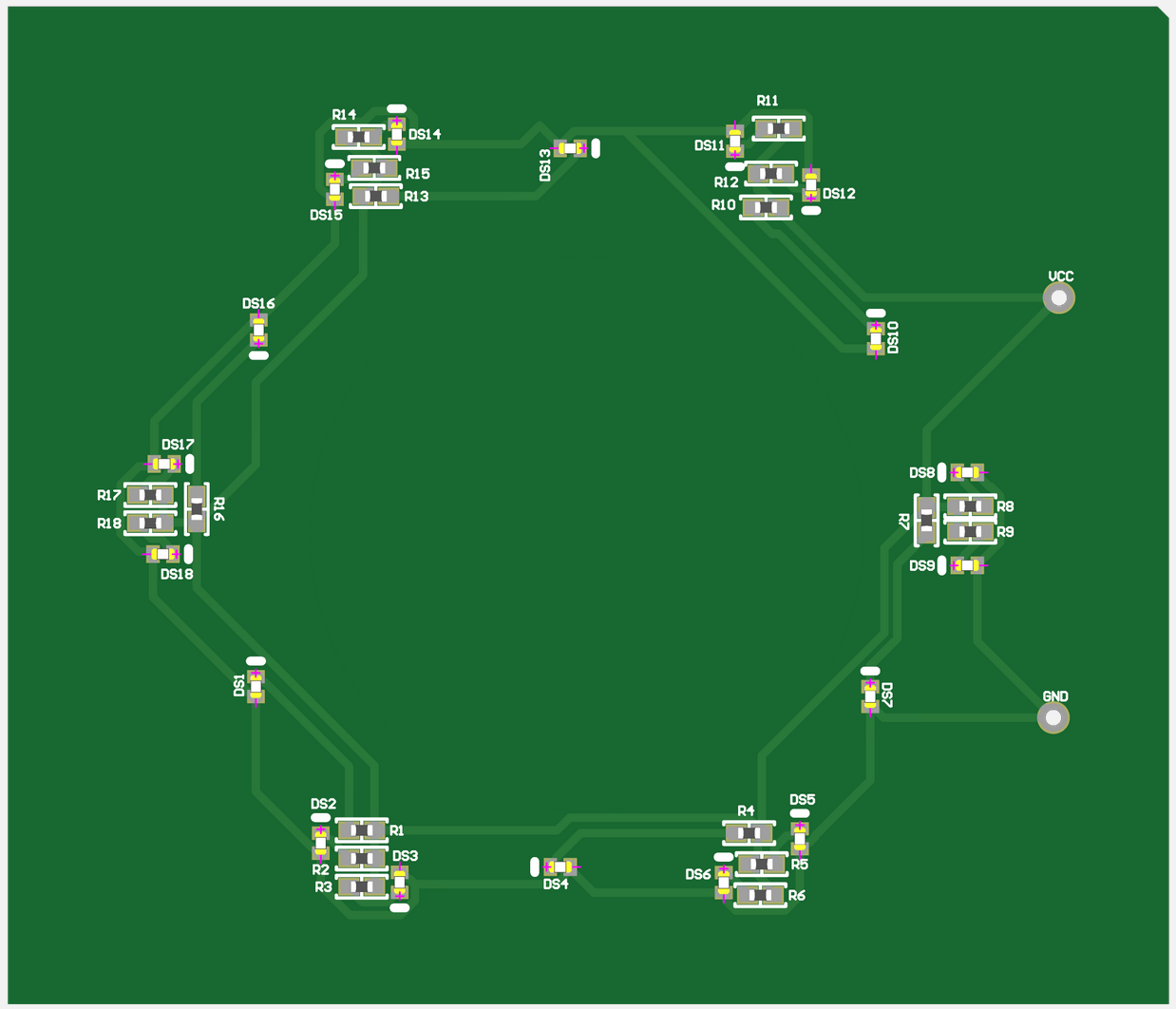
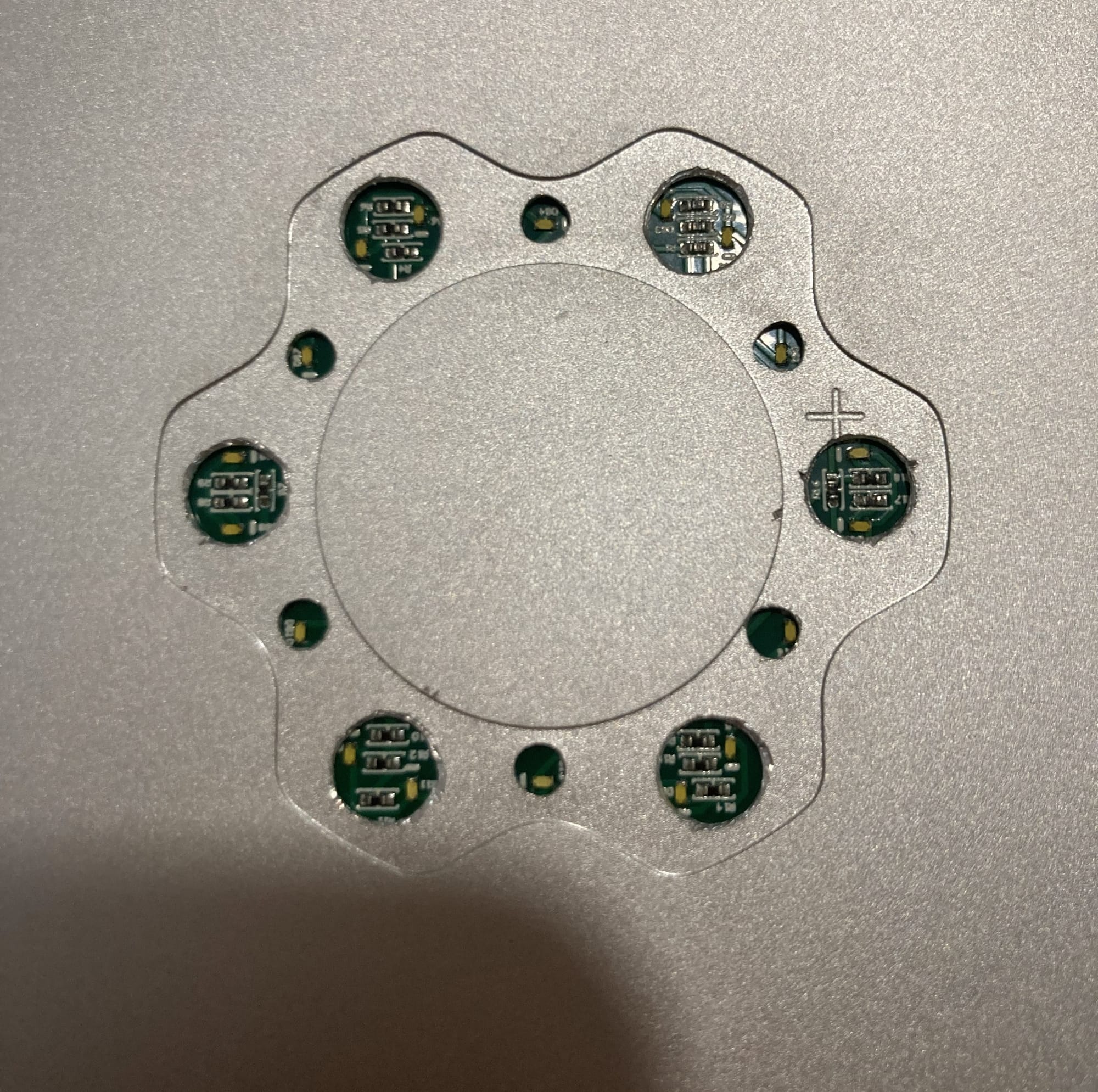
Here's what the board looks like at a tiny scale, it's really just 18 LEDs in parallel, each with a resistor. I put two LEDs each in the larger holes, because I figured that would help me spread the light out a little more, my goal was to make it as uniform as possible.
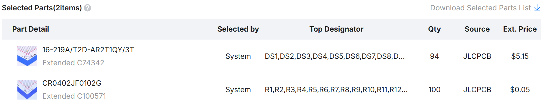
These are the parts I used, if anyone wants to duplicate my work. The qty there is because JLC manufactures 5 of the boards at a time, so even though I only needed one, I payed for (and still have) 5 of them. I had some coupons, so it was only ~$35 for all of them, which wasn't too bad. JLCPCB does the PCB manufacturing and the placement and soldering of the parts (these parts are way too small for hand-soldering), so it was only one order.
I'm not going to give a tutorial on it, but you have to be very specific with your design to get the output files needed for them to manufacture the boards for you, but I managed to get it all right (except the polarity 🙄, the GND and 3V3 inputs are labeled backwards).
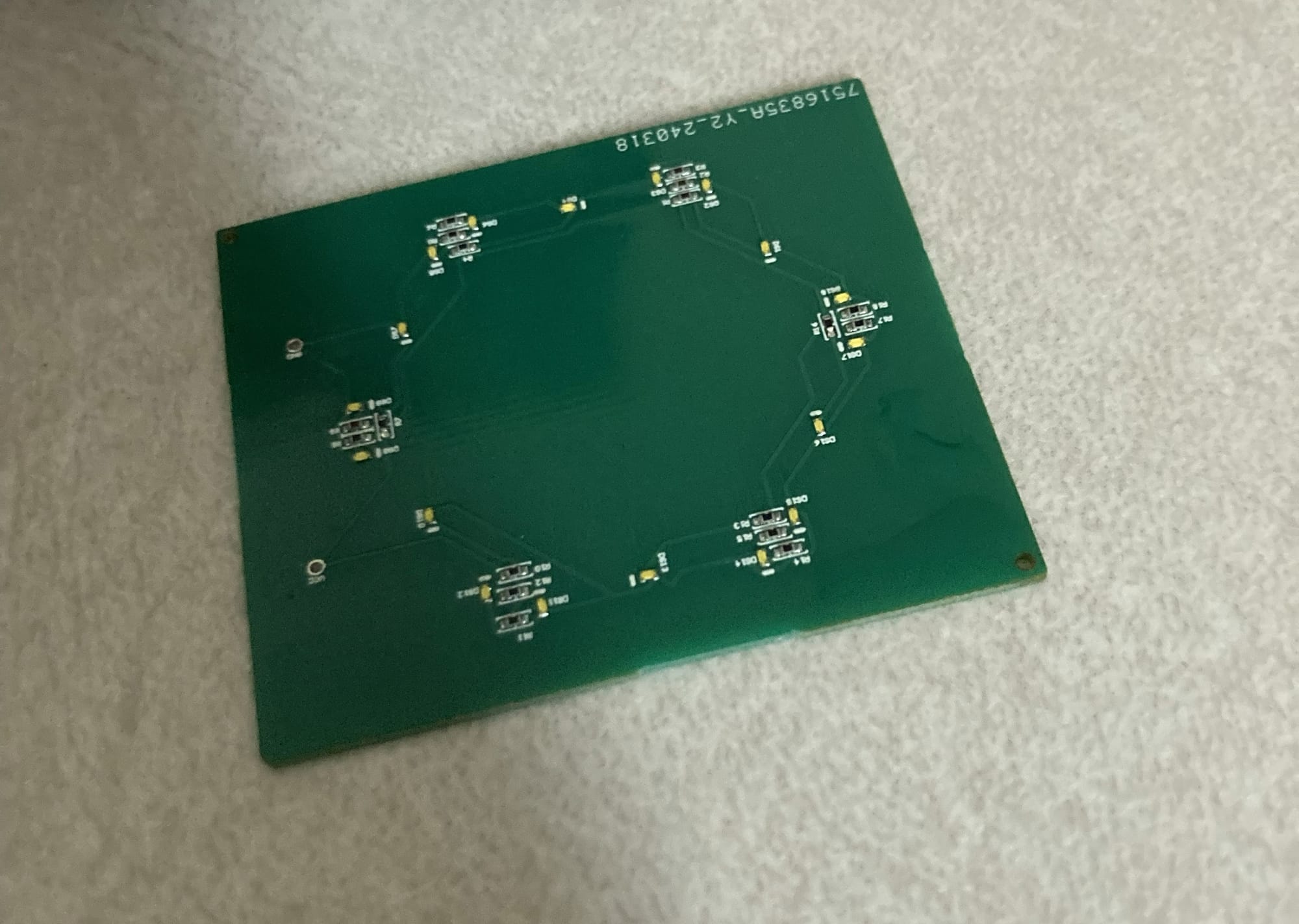
The boards came out great, and were manufactured and shipped in less than a week, which was awesome.
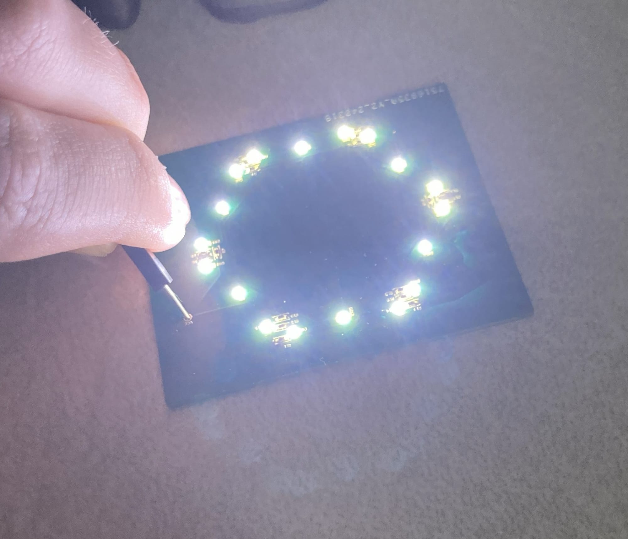
Here's the board with 3V3 held on the pins, it works great. Each of the LEDs lights up nicely, and they aren't too bright as to be problematic. I also remember checking their power draw, to see if that would be a problem, and it was something to the tune of 30 mW, which is a rounding error in a laptop; my processor can and will pull 2000 times that amount.
The lights (barely) lined up with the holes I drilled in the top, which I called good enough. The only thing left was to wire it into the laptop, and I had a good idea on how and where to do that.
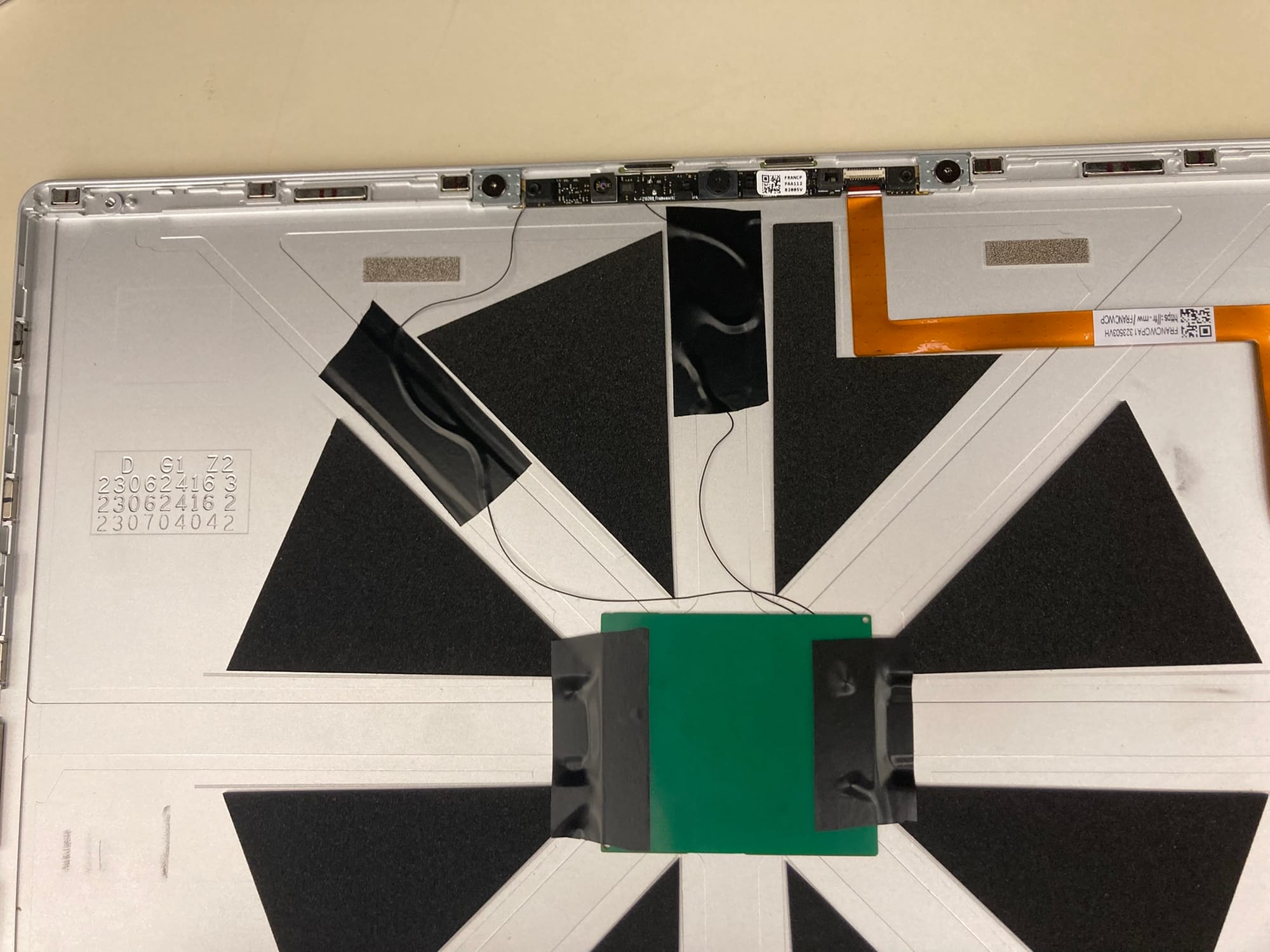
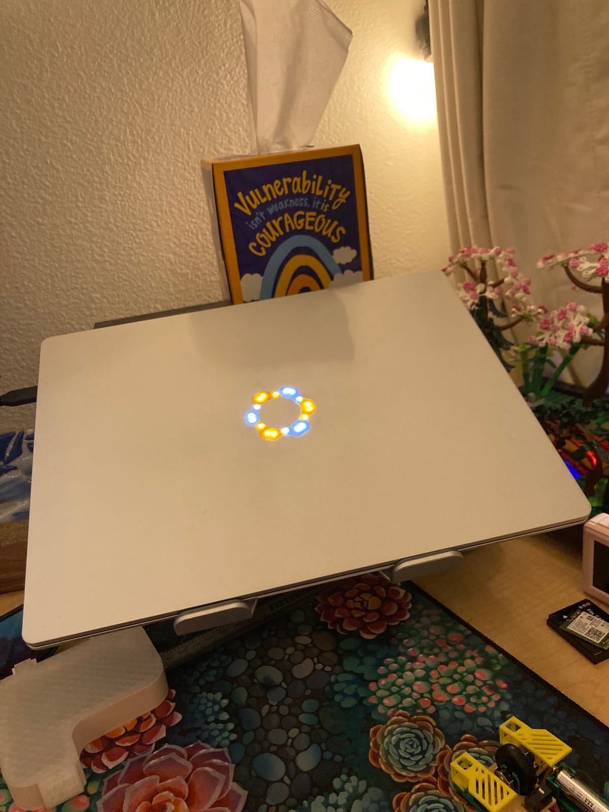
The webcam module has 3V3 running to it for power, and I was able to find big enough pads that I could solder my tiny wires (I used 36awg), and it honestly works perfectly. The 3V3 rail is only powered when the laptop is on, so when it's shut down the lid doesn't light up, but when the laptop is asleep, even with the lid closed, it'll stay on, so I can tell if I actually shut it down or it's just asleep with a glance, which is an unplanned bonus feature.
I had to trim the foam triangles a smidge to fit the PCB, but it's almost exactly the same width, and it fit in there pretty easily. That electrical tape is still what's holding the board in right now, almost a year later.
I tried a great many things for the plastic logo itself, because it was a challenge to get it translucent enough that the lights were obvious, but opaque enough that the light diffused. I never got full diffusion, but after all of my tinkering, I don't actually think it would have been possible with the space and size constraints I have.
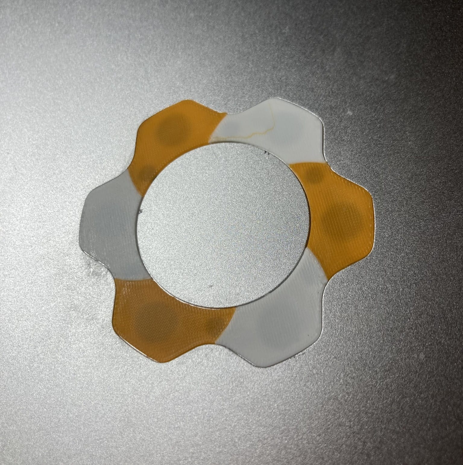
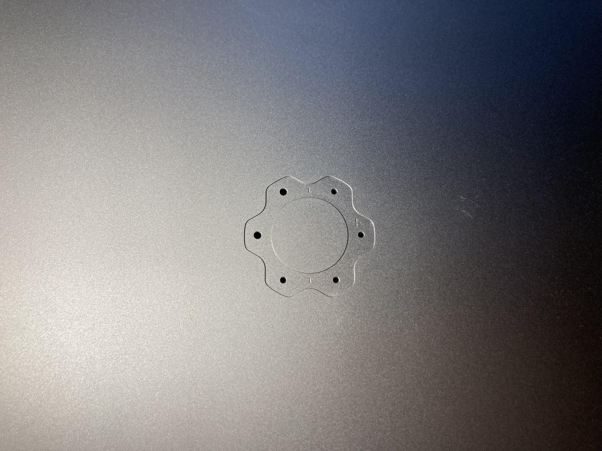
I eventually settled on this two-color spiral design, which I printed out myself using white and orange filament. I think the two-color gives it a really nice asymmetry, and I like the slight offset of the curved edges between the colors. I just printed this on my Bambu Labs A1 Mini, using a 0.2mm nozzle, so it came out fine enough detail that it is effectively impossible to tell that it's 3D-printed.
I just superglued the logo in, which is probably also helping hold the PCB in place, and I've had no trouble with it since I finished the project! I'm really happy with how it turned out, and I know it's one of one, which is a really cool designation to have.